U100K
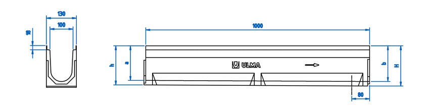
Polymer concrete Linear Drainage Channel ULMA, type U100K: External width 130mm; Internal width 100mm; Available with overall heights between 150mm and 300mm; Suitable also with 0,5% presloped or cascaded slope, to collect rain water in 1 metre long units; Integrated galvanized steel edges for lateral protection. Locking system consists of CS100 locking bar and screws.
Channel options
| CHANNEL CODE |
L
(mm) |
Alt total
(mm) |
Width (mm) | Output Diam. (mm) |
Hydraulic section
(cm) |
Units
(x pallet) |
Peso
(Kg) |
Qref
(l/s) |
||||
|---|---|---|---|---|---|---|---|---|---|---|---|---|
| Exterior | Interior | Vert. | Horiz. | |||||||||
| U100K00R | 1000mm | 150mm | 130mm | 100mm | 110.0 | 97.0 | 90.0 | 14.09 | 3.5 | DWG | ||
| U100K01 | 1000mm | 101.0 | 90.0 | 14.89125 | 6.01792 | DWG | ||||||
| U100K02 | 1000mm | 106.0 | 90.0 | 15.222515 | 6.45161 | DWG | ||||||
| U100K03 | 1000mm | 111.0 | 78.0 | 15.884 | 6.74009 | DWG | ||||||
| U100K04 | 1000mm | 116.0 | 78.0 | 15.6959 | 7.18296 | DWG | ||||||
| U100K05 | 1000mm | 120.0 | 78.0 | 16.16615 | 7.48873 | DWG | ||||||
| U100K05R | 1000mm | 175mm | 130mm | 100mm | 110.0 | 120.0 | 78.0 | 16.42531 | 5.0 | DWG | ||
| U100K06 | 1000mm | 125.0 | 65.0 | 16.6155 | 7.79986 | DWG | ||||||
| U100K07 | 1000mm | 130.0 | 65.0 | 17.0335 | 8.28576 | DWG | ||||||
| U100K08 | 1000mm | 135.0 | 65.0 | 17.81725 | 8.59833 | DWG | ||||||
| U100K09 | 1000mm | 140.0 | 65.0 | 18.112985 | 8.92735 | DWG | ||||||
| U100K10 | 1000mm | 145.0 | 65.0 | 17.956235 | 9.45759 | DWG | ||||||
| U100K10R | 1000mm | 200mm | 130mm | 100mm | 110.0 | 110.0 | 145.0 | 65.0 | 18.01371 | 6.7 | DWG | |
| U100K11 | 1000mm | 150.0 | 65.0 | 18.583235 | 9.79376 | DWG | ||||||
| U100K12 | 1000mm | 155.0 | 65.0 | 18.827765 | DWG | |||||||
| U100K13 | 1000mm | 159.0 | 65.0 | 18.96675 | DWG | |||||||
| U100K14 | 1000mm | 164.0 | 65.0 | 19.314735 | DWG | |||||||
| U100K15 | 1000mm | 169.0 | 65.0 | 19.84246 | DWG | |||||||
| U100K15R | 1000mm | 225mm | 130mm | 100mm | 110.0 | 110.0 | 169.0 | 65.0 | 19.84246 | 8.5 | DWG | |
| U100K16 | 1000mm | 174.0 | 65.0 | 19.993985 | DWG | |||||||
| U100K17 | 1000mm | 178.0 | 65.0 | 20.63875 | DWG | |||||||
| U100K18 | 1000mm | 183.0 | 52.0 | 21.126765 | DWG | |||||||
| U100K19 | 1000mm | 188.0 | 52.0 | 21.352485 | DWG | |||||||
| U100K20 | 1000mm | 193.0 | 52.0 | 22.10175 | DWG | |||||||
| U100K20R | 1000mm | 250mm | 130mm | 100mm | 110.0 | 110.0 | 193.0 | 52.0 | 22.32956 | 10.5 | DWG | |
| U100K25R | 1000mm | 275mm | 130mm | 100mm | 110.0 | 110.0 | 240.0 | 52.0 | 23.07151 | 12.6 | DWG | |
| U100K30R | 1000mm | 300mm | 130mm | 100mm | 110.0 | 110.0 | 288.0 | 52.0 | 26.14381 | 14.9 | DWG | |
Grating options
| Material | Design | Load Class | Code | How to fix | ||
|---|---|---|---|---|---|---|
| Ductile Cast Iron | Slotted (Standard) | B-125 | FNX100KCBM | 2 locking bars and 2 screws per linear metre | DWG | |
| Ductile Cast Iron | Slotted (Standard) | C-250 | FNX100KCCM | 2 locking bars and 2 screws per linear metre | DWG | |
| Ductile Cast Iron | Slotted (Heelproof) | C-250 | FNHX100KCCM | 2 locking bars and 2 screws per linear metre | DWG | |
| Galvanized Steel | Perforated | A-15 | GP100KCA | 2 locking bars and 2 screws per linear metre | DWG | |
| Galvanized Steel | Slotted (Standard) | A-15 | GN100KCA | 2 locking bars and 2 screws per linear metre | DWG | |
| Galvanized Steel | Mesh (Standard) | B-125 | GEX100KCB | 2 locking bars and 2 screws per linear metre | DWG | |
| Galvanized Steel | Mesh (Heelproof) | B-125 | GEHX100KCB | 2 locking bars and 2 screws per linear metre | DWG | |
| Stainless Steel | Slotted (Standard) | A-15 | IN100KCA | 2 locking bars and 2 screws per linear metre | DWG | |
| Stainless Steel | Perforated | A-15 | IP100KCA | 2 locking bars and 2 screws per linear metre | DWG | |
| Composite | Slotted (Heelproof) | A-15 | PNH100KCAM | 2 locking bars and 2 screws per linear metre | DWG | |
| Composite | Slotted (Heelproof) | A-15 | PNH100KCAM-GRIS | 2 locking bars and 2 screws per linear metre | DWG | |
| Composite | Mesh (Standard) | B-125 | PE100KCBM | 2 locking bars and 2 screws per linear metre | DWG | |
| SUMP UNITS AND INSTALLATION DETAILS | ||
|---|---|---|
| AK100 Sump Unit drawing | DWG | |
| Installation details. Paver | DWG | |
| Installation details. Paver onto a load-bearing slab | DWG | |
| Installation details. Asphalt | DWG | |
| Installation details. Concrete | DWG | |
| Installation details. Installation beside Kerb | DWG | |